


City-size Power Plant Gas Turbine Ducts. Extreme, Heated Forced Air Powers the Blades.
PRODUCT OVERVIEW
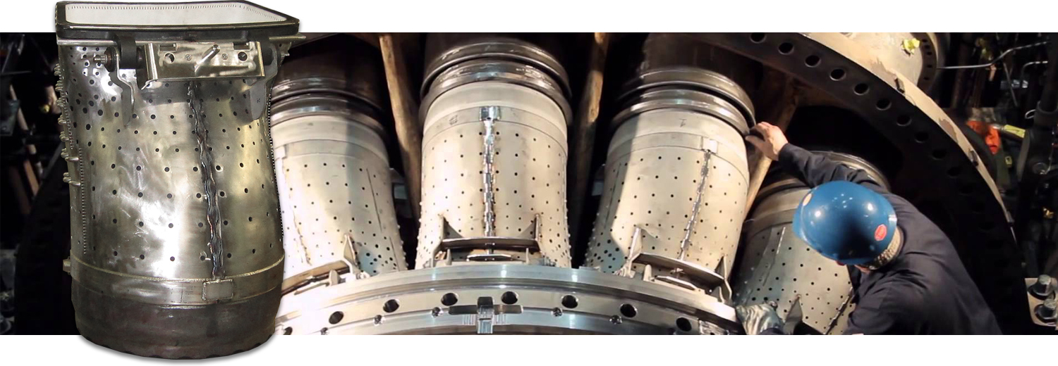
- Inner Ducts Channel Superheated, Compressed Air 24/7
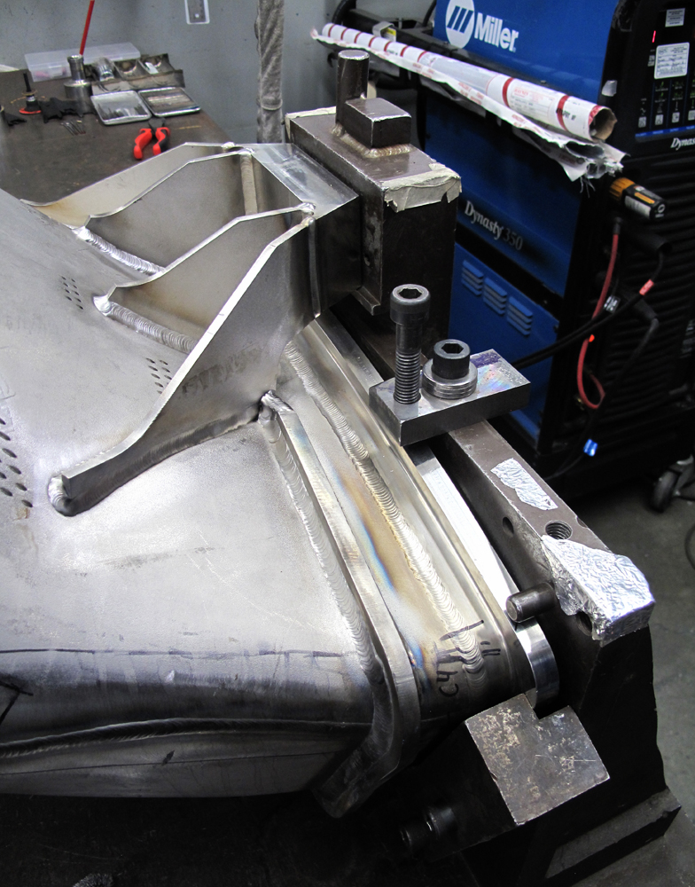
- Thick Inconel Maintains Duct Wall Integrity
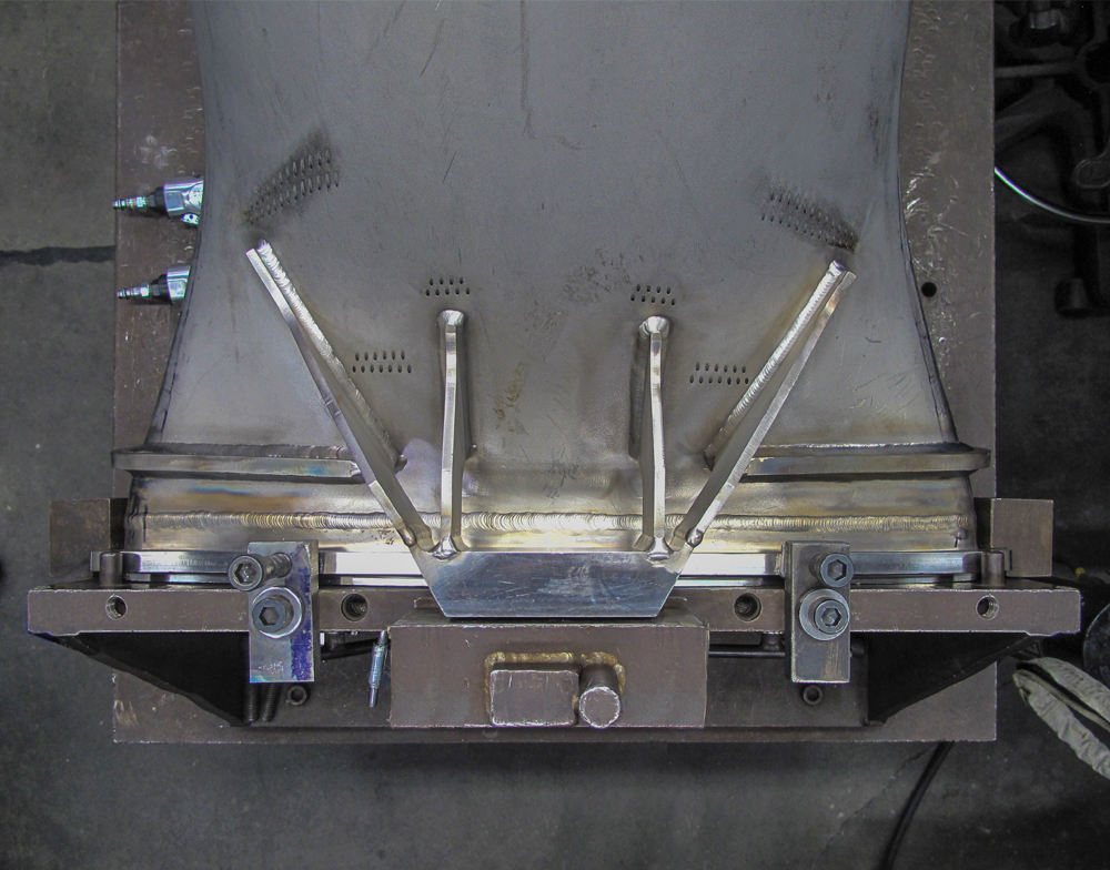
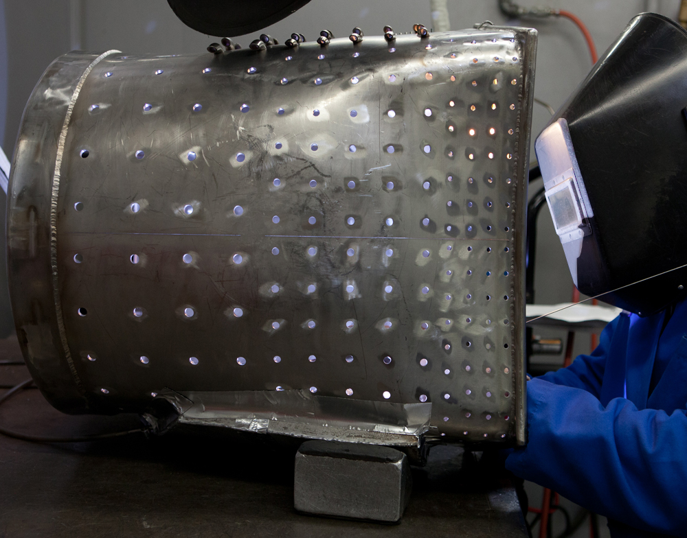
- Outer Impingement Sleeves Perforated with Precisely Placed Holes and Tubes for Cooling
- Specifications Require Extreme Tolerances for Extreme Conditions
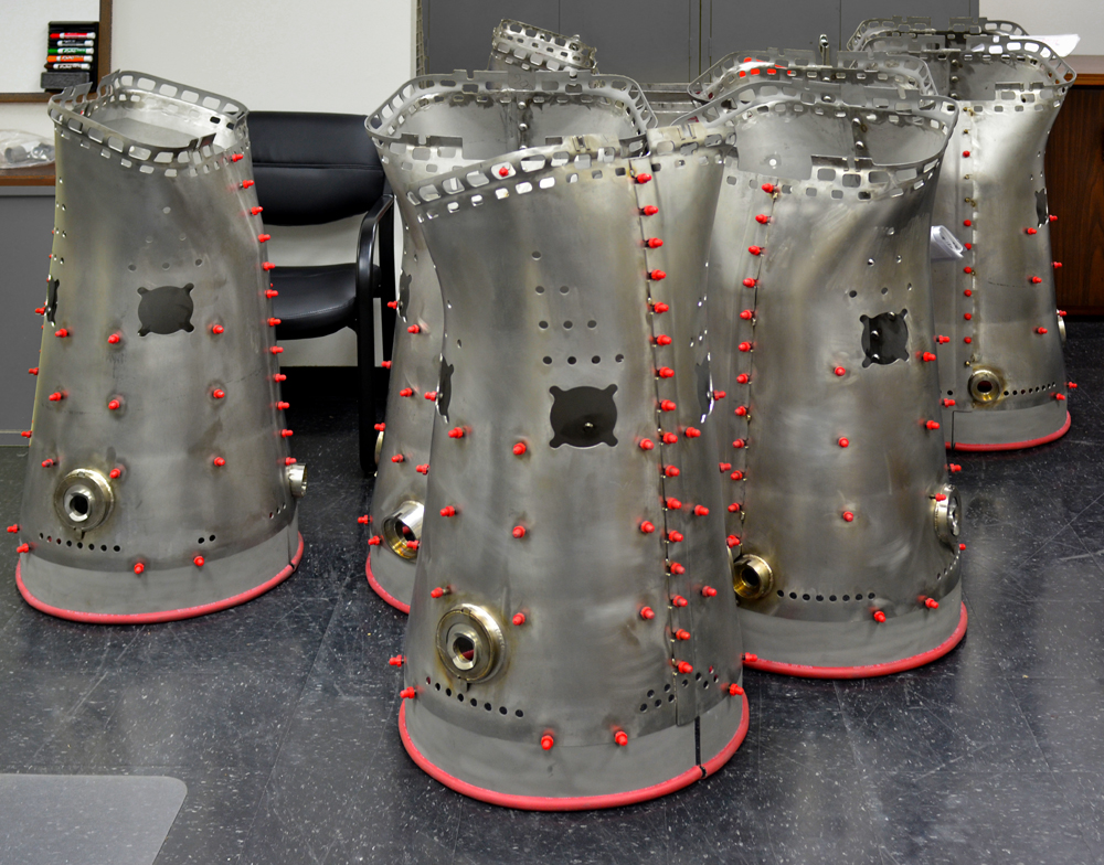
- Each Turbine Requires 8 to 12 Identical Ducts, Replicated Flawlessly in Our Shop
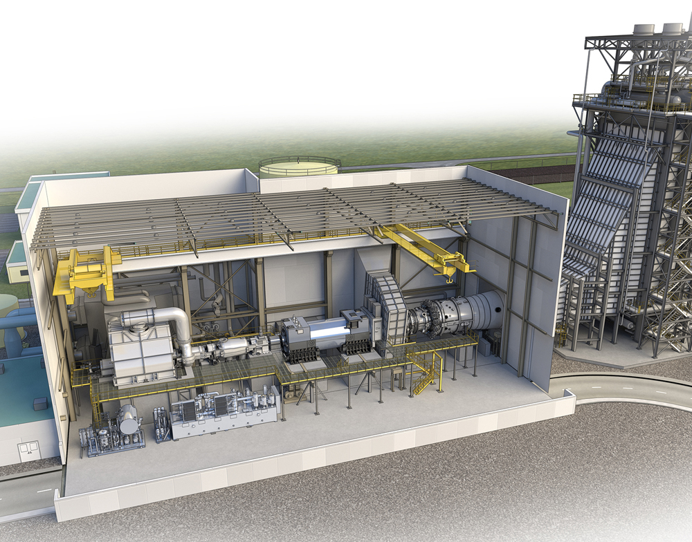
Power is the key word for these massive transition ducts and impingement sleeves, which channel huge amounts of superheated, compressed air from large combustion chambers into turbines. These systems were developed by GE based upon their jet engine technologies for aircraft. Blades inside these turbines both draw air into the system and compress it to mix with natural gas and ignite, forcefully blow through the ducts onto a second set of blades which spins the first set and also spin a core shaft which powers the generator, creating enough power for a city. Larger turbines like these generate around 500,000 horsepower, and 500 megawatts of electricity.
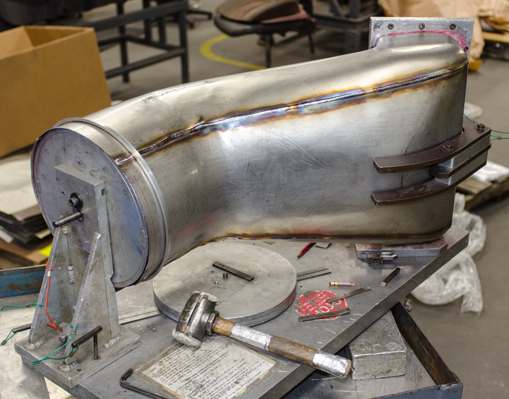
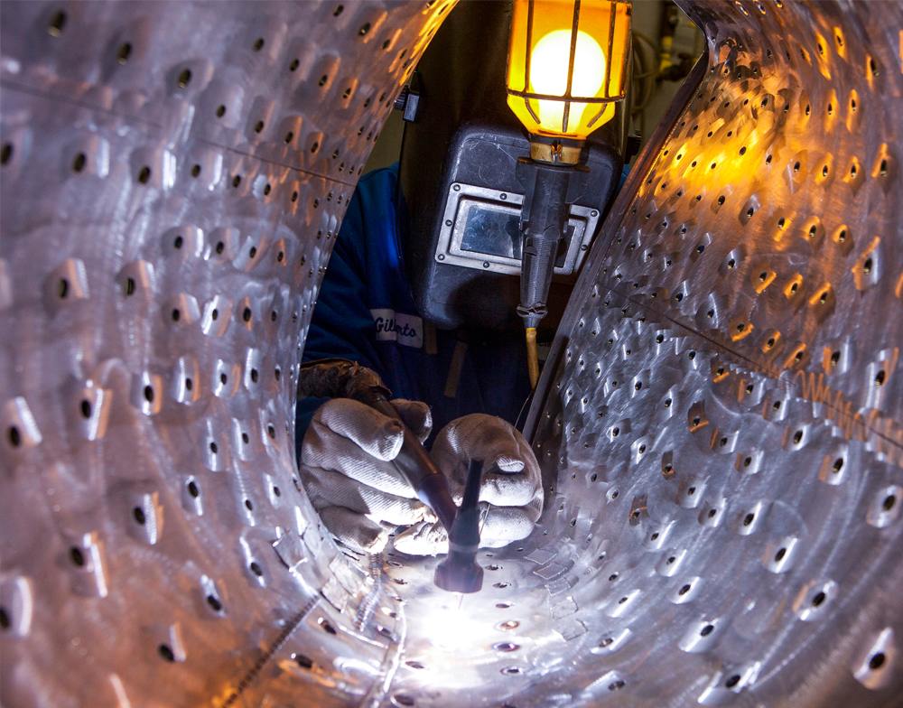
Our thick-walled Inconel ducts are constructed and welded to handle tremendous heat and pressure, 24/7. They are sheathed with sleeves which provide a uniform space surrounding the duct and have holes specifically spaced out to draw ambient air inside and circulate to cool the system.
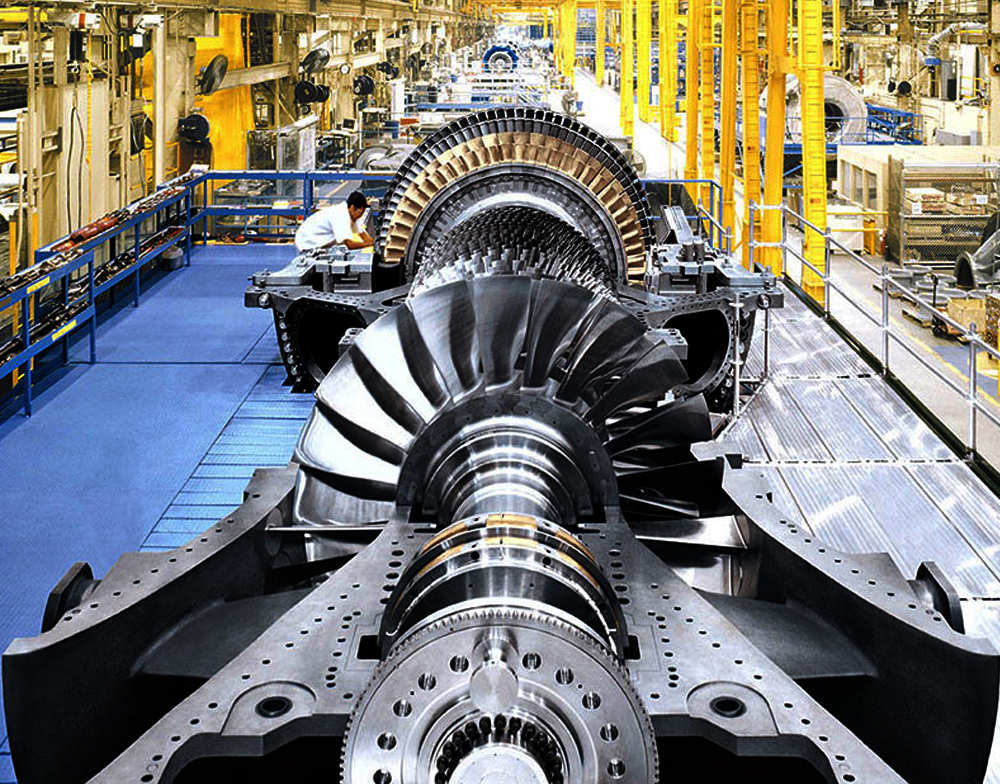
The combustion (gas) turbines in many natural-gas-fueled power plants are complex machines, but they basically involve three main sections:
- The compressor, which draws air into the engine, pressurizes it, and feeds it to the combustion chamber at speeds of hundreds of miles per hour. It is known as the cold section.
- The combustion system, typically made up of a ring of fuel injectors that inject a steady stream of fuel into combustion chambers where it mixes with the air. The mixture is burned at temperatures of more than 2000 degrees F. The combustion produces a high temperature, high pressure gas stream that enters and expands through the turbine’s transition duct section. With the following turbine, it makes up the hot section.
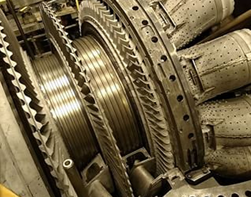
- The turbine is an intricate array of alternate stationary and rotating aerofoil-section blades. As hot combustion gas expands through the turbine, it spins the rotating blades. The rotating blades perform a dual function: they drive the compressor to draw more pressurized air into the combustion section, and they spin a generator to produce electricity.

HARNESSING ALL THAT POWER
-
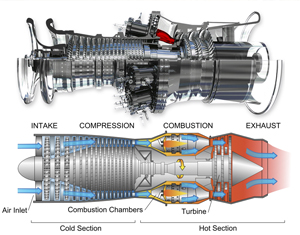 Very similar to aircraft jet engines, the gas turbine draws in air, compresses and blasts it onto fan blades, which spin the center shaft to power the generator.
 -
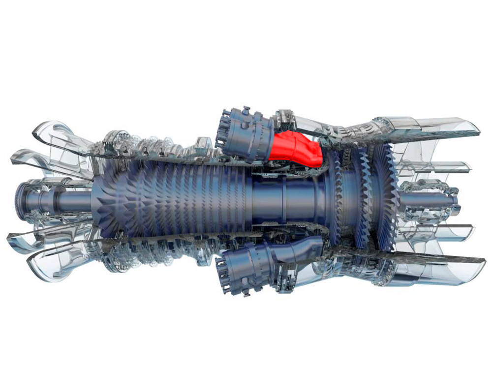
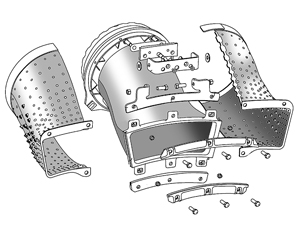 This cutaway shows the impingement sleeve and the transition duct inside.
 -
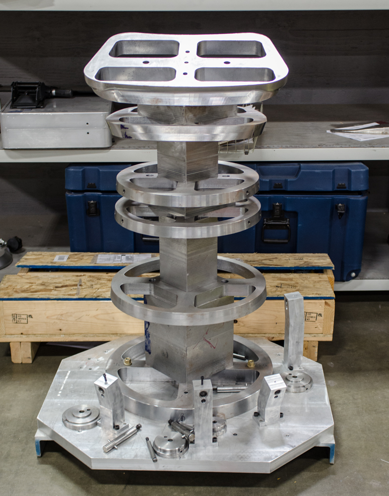
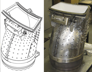 From drawing to final part.
 -
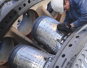 ...and final installation. This turbine has 12 identical ducts directing the heated, compressed air.
-